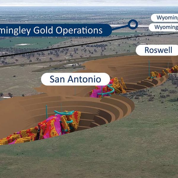
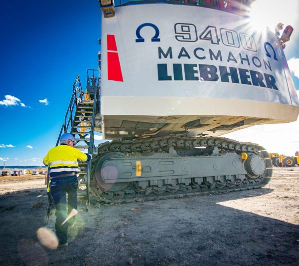
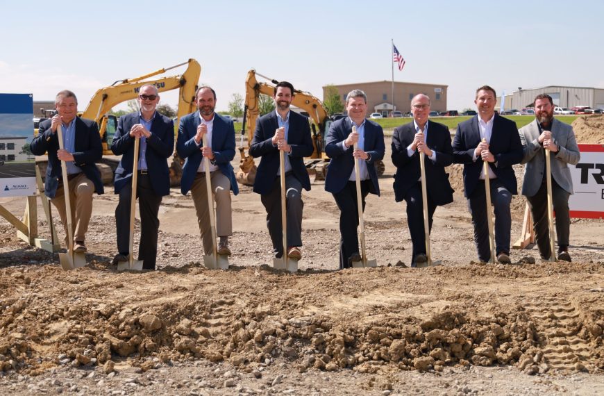
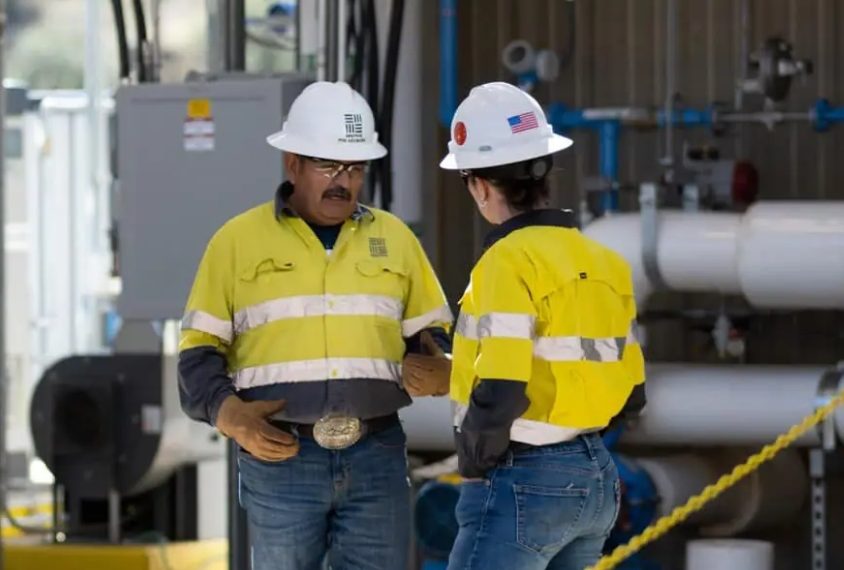
Modern conveyor design is creating demand for extremely large and expensive belts with greater tensions and power capabilities than ever before. These belts are driven by lagged pulleys, and it would be valuable to prove this lagging will perform under the increased tension and drive requirements.
![]() |
The lagging test fixture (left) and the fixture in use (right). The test apparatus was designed by Flexco chief engineer Brett DeVries. |
For decades lagging has been used to both protect conveyor pulleys and to increase the available friction for driving the conveyor belt. Today lagging is available in various embodiments with differing stated capabilities and strengths.
A primary consideration in the choice of lagging is the coefficient of friction. Designers use the friction coefficient in the Euler Capstan equation to calculate the drive capacity of the conveyor, so the behaviour of lagging friction under real world conditions is of extreme interest. As belt technology innovates with increasing tensions and more power delivered through the drive pulleys, a correct understanding of the source of friction is necessary.
NEW conveyor design tools using powerful algorithms can predict the dynamics of increasingly long distance and high tension conveyor belts. Improved power sources like 6000kW gearless drives allow more throughput power on a single pulley than ever before.
Both are allowing engineers to design larger and more profitable conveyors, which are more demanding of all the components. Pulley lagging is no exception.
Pulley lagging is available in a myriad of styles and materials. The most common types are autoclave rubber, sheet rubber, strip rubber and ceramic imbedded in rubber (CIR). All exhibit different coefficients of friction by nature of their design, creating a confusing choice for the conveyor designer. Some established design charts for friction exist like those contained in CEMA’s Belt Conveyors for Bulk Materials 7th Ed., and the DIN 22101 standard, but they are generalised, come from best practices and assume a constant coefficient of friction.
In contrast, values published by lagging manufactures may vary significantly from the charts. Additionally, there is no standardised test for determining the lagging friction coefficient or an industry standard for applying a safety factor against slippage
When Flexco chief engineer Brett DeVries started researching lagging friction coefficients, he was unable to find any literature on the best practice for how to measure it. He set about designing a test apparatus for measuring lagging friction which works by taking a small belt and gluing it to two steel plates. He then sticks in on an apparatus that squeezes two pieces of lagging against it on either side. The technique can also work in reverse by glueing lagging to the steel plate and pressing the belt up against the lagging.
He said the apparatus measured the force that the belt was squeezing against the lagging. “When the steel plate is pulled out upward from the two pieces of belt, the force it takes to extract that as the plate begins to be drawn out is also measured.” He said the technique allowed people to measure the force displacement simultaneously and create a plot of what force and displacement looked like.
The apparatus allows for friction coefficients to be measured under uniform pressurised loading. Applied pressures range from 34.5kPa to 690 kPa, including some measurements to 827 kPa for various lagging types.
The result is a strong dependence between the coefficient of friction and pressure. This is contrary to the industry practice of assuming a constant friction factor and utilising the Euler Capstan equation to calculate allowable tension ratios around the drive pulley.
An attempt is made to modify the Euler Capstan equation to incorporate pressure dependent friction, but is shown to be unsolvable. As a result, an approximation method based on the generated shear stress, or traction, at the lagging surface is presented.
The data presented suggests the existence of a maximum available traction, regardless of increasing pressure, for each lagging design. Using the approximation method, it is shown that belt tension, lagging type, wrap angle and pulley diameter are all factors affecting drive capacity. It is also shown that changes in the pulley diameter, wrap angle, or lagging type can have a strong influence on the minimum tension rating required for the conveyor belt.
Brett DeVries said more studies using a variety of known algorithms on an array of mediums and in varying situations were still required to innovate belt technology and optimise operations in mining.
He said the final product would be useful for companies wanting to carry out in situ repair work for their lagging. “It’s meant to be welded to the pulley so that pulleys don’t have to be removed from service in order to be re-lagged.”
This Flexco study leads the way to understand not only lagging nature of belt conveyors but to assist in designing better so as to ensure customers receive the safest and reliable product for their operations.
For more information or a copy of the study contact Cheryl at Flexco – [email protected]